 Prohibition or Restriction of Certain Conventional Weapons Act, 2008
R 385
Merchant Shipping Act, 1951 (Act No. 57 of 1951)SchedulesSecond ScheduleProtocol of 1978 Relating to the International Convention for the Safety of Life at Sea, 1974AnnexChapter VI : Carriage of GrainPart C — Grain Fittings and SecuringSection I — Strength of Grain Fittings |
| (A) | GENERAL |
| (a) | Timber. |
All timber used for grain fittings shall be of good sound quality and of a type and grade which has been proved to be satisfactory for this purpose. The actual finished dimensions of the timber shall be in accordance with the dimensions hereinafter specified in this Part. Plywood of an exterior type bonded with waterproof glue and fitted so that the direction of the grain in the face plies is perpendicular to the supporting uprights or binder may be used provided that its strength is equivalent to that of solid timber of the appropriate scantlings.
| (b) | Working stresses. |
When calculating the dimensions of divisions loaded on one side, using the Tables in paragraphs (a) and (b) and Subsection (C) of this Section, the following working stresses should be adopted:
For divisions of steel 2 000 kg per square cm
For divisions of wood 160 kg per square cm
| (c) | Other materials. |
Materials other than wood or steel may be approved for such divisions provided that proper regard has been paid to their mechanical properties.
| (d) | Uprights. |
| (i) | Unless means are provided to prevent the ends of uprights being dislodged from their sockets, the depth of housing at each end of each upright shall be not less than 75 mm. If an upright is not secured at the top, the uppermost shore or stay shall be fitted as near thereto as is practicable. |
| (ii) | The arrangements provided for inserting shifting boards by removing a part of the cross-section of an upright shall be such that the local level of stresses is not unduly high. |
| (iii) | The maximum bending moment imposed upon an upright supporting a division loaded on one side shall normally be calculated assuming that the ends of the uprights are freely supported. However, if an Administration is satisfied that any degree of fixity assumed will be achieved in practice, account may be taken of any reduction in the maximum bending moment arising from any degree of fixity provided at the ends of the upright. |
| (e) | Composite section. |
Where uprights, binders or any other strength members are formed by two separate sections, one fitted on each side of a division and interconnected by through bolts at adequate spacing, the effective section modules shall be taken as the sum of the two moduli of the separate sections.
| (f) | Partial division. |
Where divisions do not extend to the full depth of the hold such divisions and their uprights shall be supported or stayed so as to be as efficient as those which do extend to the full depth of the hold.
(B) DIVISIONS LOADED ON BOTH SIDES
| (a) | Shifting boards. |
| (i) | Shifting boards shall have a thickness of not less than 50 mm and shall be fitted grain-tight and where necessary supported by uprights. |
| (ii) | The maximum unsupported span for shifting boards of various thicknesses shall be as follows: |
|
Thickness |
Maximum unsupported span |
|
mm |
metres |
|
50 |
2,5 |
|
60 |
3,0 |
|
70 |
3,5 |
|
80 |
4,0 |
If thicknesses greater than these are provided the maximum unsupported span will vary directly with the increase in thickness.
| (iii) | The ends of all shifting boards shall be securely housed with 75 mm minimum bearing length. |
| (b) | Other materials. |
Divisions formed by using materials other than wood shall have a strength equivalent to the shifting boards required in paragraph (a) of this subsection.
| (c) | Uprights. |
| (i) | Steel uprights used to support divisions loaded on both sides shall have a section modulus given by: |
![]()
Where—
W = section modulus in cm3
a = horizontal span between uprights in metres.
The Section modulus per metre span W1 shall not be less than that given by the formula:
![]()
Where—
h1 is the vertical unsupported span in metres and shall be taken as the maximum value of the distance between any two adjacent stays or between the stay or either end of the upright. Where this distance is less than 2,4 metres the respective modulus shall be calculated as if the actual value was 2,4 metres.
| (ii) | The moduli of wood uprights shall be determined by multiplying by 12,5 the corresponding moduli for steel uprights. If other materials are used their moduli shall be at least that required for steel increased in proportion to the ratio of the permissible stresses for steel to that of the material used. In such cases attention shall be paid also to the relative rigidity of each upright to ensure that the deflection is not excessive. |
| (iii) | The horizontal distance between uprights shall be such that the unsupported spans of the shifting boards do not exceed the maximum span specified in subparagraph (ii) of paragraph (a) of this Subsection. |
| (d) | Shores. |
| (i) | Wood shores, when used, shall be in a single piece and shall be securely fixed at each end and heeled against the permanent structure of the ship except that they shall not bear directly against the side plating of the ship. |
| (ii) | Subject to the provisions of subparagraphs (iii) and (iv) below, the minimum size of wood shores shall be as follows: |
|
Length of shore in metres |
Rectangular section |
Diameter of circular section |
|
|
mm |
mm |
|
Not exceeding 3 m |
50 x 100 |
140 |
|
Over 3 m but not exceeding 5 m |
150 x 150 |
165 |
|
Over 5 m but not exceeding 6 m |
150 x 150 |
180 |
|
Over 6 m but not exceeding 7 m |
200 x 150 |
190 |
|
Over 7 m but not exceeding 8 m |
200 x 150 |
200 |
|
Exceeding 8 m |
200 x 150 |
215 |
Shores of 7 metres or more in length shall be securely bridged at approximately mid-length (iii) When the horizontal distance between the uprights differs significantly from 4 metres, the moments of inertia of the shores may be changed in direct proportion.
| (iv) | Where the angle of the shore to the horizontal exceeds 10 degrees the next larger shore to that required by subparagraph (ii) of this paragraph shall be fitted provided that in no case shall the angle between any shore and the horizontal exceed 45 degrees. |
| (e) | Stays. |
Where stays are used to support divisions loaded on both sides, they shall be fitted horizontally or as near thereto as practicable, well secured at each end and formed of steempune sizes of the wire rope shall be determined assuming that the divisions and upright which the stay supports are uniformly loaded at 500 kg/m2. The working load so assumed in the stay shall not exceed one-third of its breaking load.
| (C) | DIVISIONS LOADED ON ONE SIDE ONLY |
| (a) | Longitudinal divisions. |
The load in kg per metre length of the division shall be taken to be as follows:
TABLE I
B (m)
|
h (m) |
2 |
3 |
4 |
5 |
6 |
7 |
8 |
10 |
|
1,5 |
850 |
900 |
1 010 |
1 225 |
1 500 |
1 770 |
2 060 |
2 645 |
|
2,0 |
1 390 |
1 505 |
1 710 |
1 985 |
2 295 |
2 605 |
2 930 |
3 590 |
|
2,5 |
1 985 |
2 160 |
2 430 |
2 740 |
3 090 |
3 435 |
3 800 |
4 535 |
|
3,0 |
2 615 |
2 845 |
3 150 |
3 500 |
3 885 |
4 270 |
4 670 |
5 480 |
|
3,5 |
3 245 |
3 525 |
3 870 |
4 255 |
4 680 |
5 100 |
5 540 |
6 425 |
|
4,0 |
3 890 |
4 210 |
4 590 |
5 015 |
5 475 |
5 935 |
6 410 |
7 370 |
|
4,5 |
4 535 |
4 890 |
5 310 |
5 770 |
6 270 |
6 765 |
7 280 |
8 315 |
|
5,0 |
5 185 |
5 570 |
6 030 |
6 530 |
7 065 |
7 600 |
8 150 |
9 260 |
|
6,0 |
6 475 |
6 935 |
7 470 |
8 045 |
8 655 |
9 265 |
9 890 |
11 150 |
|
7,0 |
7 765 |
8 300 |
8 910 |
9 560 |
10 245 |
10 930 |
11 630 |
13 040 |
|
8,0 |
9 055 |
9 665 |
10 350 |
11 075 |
11 835 |
12 595 |
13 370 |
14 930 |
|
9,0 |
10 345 |
11 030 |
11 790 |
12 590 |
13 425 |
14 260 |
15 110 |
16 820 |
|
10,0 |
11 635 |
12 395 |
13 230 |
14 105 |
15 015 |
15 925 |
16 850 |
18 710 |
| B = | transverse extent of the bulk grain in metres. |
| h = | height of grain in metres from the bottom of the division. |
For other values of h or B the loads shall be determined by linear interpolation or extrapolation as necessary.
| (b) | Transverse divisions. |
The load in kg per metre length of the division shall be taken to be as follows:
TABLE II
L (m)
|
h (m) |
2 |
3 |
4 |
5 |
6 |
7 |
8 |
10 |
12 |
14 |
16 |
|
1,5 |
670 |
690 |
730 |
780 |
835 |
890 |
935 |
1 000 |
1 040 |
1 050 |
1 050 |
|
2,0 |
1 040 |
110 |
1 170 |
1 245 |
1 325 |
1 400 |
1 470 |
1 575 |
1 640 |
1 660 |
1 660 |
|
2,5 |
1 460 |
1 565 |
1 675 |
1 780 |
1 880 |
1 980 |
2 075 |
2 210 |
2 285 |
2 305 |
2 305 |
|
3,0 |
1 925 |
2 065 |
2 205 |
2 340 |
2 470 |
2 590 |
2 695 |
2 845 |
2 925 |
2 950 |
2 950 |
|
3,5 |
2 425 |
2 605 |
2 770 |
2 930 |
3 075 |
3 205 |
3 320 |
3 480 |
3 570 |
3 595 |
3 595 |
|
4,0 |
2 950 |
3 160 |
3 355 |
3 535 |
3 690 |
3 830 |
3 950 |
4 120 |
4 210 |
4 235 |
4 240 |
|
4,5 |
3 495 |
3 725 |
3 940 |
4 130 |
4 295 |
4 440 |
4 565 |
4 750 |
4 850 |
4 880 |
4 885 |
|
5,0 |
4 050 |
4 305 |
4 535 |
4 735 |
4 910 |
5 060 |
5 190 |
5 385 |
5 490 |
5 525 |
5 530 |
|
6,0 |
5 175 |
5 465 |
5 720 |
5 945 |
6 135 |
6 300 |
6 445 |
6 655 |
6 775 |
6 815 |
6 825 |
|
7,0 |
6 300 |
6 620 |
6 905 |
7 150 |
7 365 |
7 445 |
7 700 |
7 930 |
8 055 |
8 105 |
8 115 |
|
8,0 |
7 425 |
7 780 |
8 090 |
8 360 |
8 590 |
8 685 |
8 950 |
9 200 |
9 340 |
9 395 |
9 410 |
|
9,0 |
8 550 |
8 935 |
9 275 |
9 565 |
9 820 |
9 930 |
10 205 |
10 475 |
10 620 |
10 685 |
10 705 |
|
10,0 |
9 680 |
10 095 |
10 460 |
10 770 |
11 045 |
11 460 |
11 460 |
11 745 |
11 905 |
11 975 |
11 997 |
| B = | transverse extent of the bulk grain in metres. |
| h = | height of grain in metres from the bottom of the division†. |
For other values of h or L the loads shall be determined by linear interpolation or extrapolation as necessary.
| (c) | Vertical distribution of the loads. |
The total load per unit length of divisions shown in the Tables I and II above may, if considered necessary, be assumed to have a trapezoidal distribution with height. In such cases, the reaction loads at the upper and lower ends of a vertical member or upright are not equal. The reaction loads at the upper end expressed as percentages of the total load supported by the vertical member or upright shall be taken to be those shown in Tables III and IV below.
TABLE III
LONGITUDINAL DIVISIONS LOADED ON ONE SIDE ONLY
Bearing Reaction at the Upper End of Upright as Percentage of Load (Table I)
B (m)
|
h (m) |
2 |
3 |
4 |
5 |
6 |
7 |
8 |
10 |
|
1,5 |
43,3 |
45,1 |
45,9 |
46,2 |
46,2 |
46,2 |
46,2 |
46,2 |
|
2,0 |
44,5 |
46,7 |
46,6 |
47,8 |
47,8 |
47,8 |
47,8 |
47,8 |
|
2,5 |
45,4 |
47,6 |
48,6 |
48,8 |
48,8 |
48,8 |
48,8 |
48,8 |
|
3,0 |
46,0 |
48,3 |
49,2 |
49,4 |
49,4 |
49,4 |
49,4 |
49,4 |
|
3,5 |
46,5 |
48,8 |
49,7 |
49,8 |
49,8 |
49,8 |
49,8 |
49,8 |
|
4,0 |
47,0 |
49,1 |
49,9 |
50,1 |
50,1 |
50,1 |
50,1 |
50,1 |
|
4,5 |
47,4 |
49,4 |
50,1 |
50,2 |
50,2 |
50,2 |
50,2 |
50,2 |
|
5,0 |
47,7 |
49,4 |
50,1 |
50,2 |
50,2 |
50,2 |
50,2 |
50,2 |
|
6,0 |
47,9 |
49,5 |
50,1 |
50,2 |
50,2 |
50,2 |
50,2 |
50,2 |
|
7,0 |
47,9 |
49,5 |
50,1 |
50,2 |
50,2 |
50,2 |
50,2 |
50,2 |
|
8,0 |
47,9 |
49,5 |
50,1 |
50,2 |
50,2 |
50,2 |
50,2 |
50,2 |
|
9,0 |
47,9 |
49,5 |
50,1 |
50,2 |
50,2 |
50,2 |
50,2 |
50,2 |
|
10,0 |
47,9 |
49,5 |
50,1 |
50,2 |
50,2 |
50,2 |
50,2 |
50,2 |
For other values of h or L the loads shall be determined by linear interpolation or extrapolation as necessary.
B = transverse extent of the bulk grain in metres.
TABLE IV
TRANSVERSE DIVISIONS LOADED ON ONE SIDE ONLY
Bearing Reaction at the Upper End of Upright as Percentage of Load (Table II)
L (m)
|
h (m) |
2 |
3 |
4 |
5 |
6 |
7 |
8 |
10 |
12 |
14 |
16 |
|
1,5 |
37,3 |
38,7 |
39,7 |
40,6 |
41,4 |
42,1 |
52,6 |
43,6 |
44,3 |
44,8 |
45,0 |
|
2,0 |
39,6 |
40,6 |
41,4 |
42,1 |
42,7 |
43,1 |
43,6 |
44,3 |
44,7 |
45,0 |
45,2 |
|
2,5 |
41,0 |
41,8 |
42,5 |
43,0 |
43,5 |
43,8 |
44,2 |
44,7 |
45,0 |
45,2 |
45,2 |
|
3,0 |
42,1 |
42,8 |
43,3 |
43,8 |
44,2 |
44,5 |
44,7 |
45,0 |
45,2 |
45,3 |
45,3 |
|
3,5 |
42,9 |
43,5 |
43,9 |
44,3 |
44,6 |
44,8 |
45,0 |
45,2 |
45,3 |
45,3 |
45,3 |
|
4,0 |
43,5 |
44,0 |
44,4 |
44,7 |
44,9 |
45,0 |
45,2 |
45,4 |
45,4 |
45,4 |
45,4 |
|
5,0 |
43,9 |
44,3 |
44,6 |
44,8 |
45,0 |
45,2 |
45,3 |
45,5 |
45,6 |
45,5 |
45,5 |
|
6,0 |
44,2 |
44,5 |
44,8 |
45,0 |
45,2 |
45,3 |
45,4 |
45,6 |
45,6 |
45,6 |
45,6 |
|
7,0 |
44,3 |
44,6 |
44,9 |
45,1 |
45,4 |
45,4 |
45,4 |
45,6 |
45,6 |
45,6 |
45,6 |
|
8,0 |
44,3 |
44,6 |
44,9 |
45,1 |
45,3 |
45,3 |
45,4 |
45,5 |
45,6 |
45,6 |
45,6 |
|
9,0 |
44,6 |
44,9 |
45,1 |
45,3 |
45,4 |
45,5 |
45,6 |
45,6 |
45,6 |
45,6 |
45,6 |
|
10,0 |
44,3 |
44,6 |
44,9 |
45,1 |
45,3 |
45,4 |
45,5 |
45,6 |
45,6 |
45,6 |
45,6 |
| L = | longitudinal extent of the bulk grain in metres. |
For other values of h or L the reaction loads shall be determined by linear interpolation or extrapolation as necessary.
The strength of the end connections of such vertical members or uprights may be calculated on the basis of the maximum load likely to be imposed at either end. These loads are as follows:
Longitudinal Divisions:
Maximum load at the top 50 per cent of the appropriate total load from Table I
Maximum load at the bottom 55 per cent of the appropriate total load from Table I
Transverse Divisions:
Maximum load at the top 45 per cent of the appropriate total load from Table II
Maximum load at the bottom 45 per cent of the appropriate total load from Table II
The thickness of horizontal wooden boards may also be determined having regard to the vertical distribution of the loading represented by Tables III and IV above and in such cases
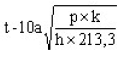
Where—
| t = | thickness of board in mm; |
| a = | horizontal span of the board i.e. distance between uprights in metres; |
| h = | head of grain to the bottom of the division in metres; |
| p = | total load per unit length derived from Table I or II in kilogrammes; |
| k = | factor dependent upon vertical distribution of the loading. |
When the vertical distribution of the loading is assumed to be uniform, i.e. rectangular, k shall be taken as equal to 1.0. For a trapezoidal distribution
![]()
Where—
R is the upper end bearing reaction taken from Table III or IV.
| (d) | Stays or shores. |
The sizes of stays and shores shall be so determined that the loads derived from Tables I and II in the preceding paragraphs (a) and (b) shall not exceed one-third of the breaking loads.
| (D) | SAUCERS |
When a saucer is used to reduce the heeling moments in a “filled compartment”, its depth, measured from the bottom of the saucer to the deck line, shall be as follows:
For ships with a moulded breadth of up to 9,1 metres, not less than 1,2 metres. For ships with a moulded breadth of 18,3 metres or more, not less than 1,8 metres.
For ships with a moulded breadth between 9,1 metres and 18,3 metres, the minimum depth of the saucer shall be calculated by interpolation.
The top (mouth) of the saucer shall be formed by the underdeck structure in the way of the hatchway, i.e. hatchside girders or coamings and hatchend beams. The saucer and hatchway above shall be completely filled with bagged grain or other suitable cargo laid down on a separation cloth or its equivalent and stowed tightly against adjacent structures and the portable hatchway beams if the latter are in place.
| (E) | BUNDLING OF BULK |
As an alternative to filling the saucer with bagged grain or other suitable cargo a bundle of bulk grain may be used provided that—
| (a) | the saucer is lined with a material acceptable to the Administration having a tensile strength of not less than 274 kg per 5 cm strip and which is provided with suitable means for securing at the top; |
| (b) | as an alternative to paragraph (a) above a material acceptable to the Administration having a tensile strength of not less than 137 kg per 5 cm strip may be used if the saucer is constructed as follows: |
Athwartship lashings acceptable to the Administration shall be placed inside the saucer formed in the bulk grain at intervals of not more than 2,4 metres. These lashings shall be of sufficient length to permit being drawn up tight and secured at the top of the saucer; dunnage not less than 25 mm in thickness or other suitable material of equal strength and between 150 to 300 mm in width shall be placed fore and aft over these lashings to prevent the cutting or chafing of the material which shall be placed thereon to line the saucer;
| (c) | the saucer shall be filled with bulk grain and secured at the top except that when using material approved under paragraph (b) above further dunnage shall be laid on top after lapping the material before the saucer is secured by setting up the lashings; |
| (d) | if more than one sheet of material is used to line the saucer they shall be joined at the bottom either by sewing or a double lap; |
| (e) | the top of the saucer shall be coincidental with the bottom of the beams when these are in place and suitable general cargo or bulk grain may be placed between the beams on top of the saucer. |
| (F) | SECURING HATCH COVERS OF FILLED COMPARTMENTS |
If there is no bulk grain or other cargo above a “filled compartment” the hatch covers shall be secured in an approved manner having regard to the weight and permanent arrangements provided for securing such covers.
The documents of authorization issued under Regulation 10 of this Chapter shall include reference to the manner of securing considered necessary by the Administration issuing such documents.