 Prevention of and Treatment for Substance Abuse Act, 2008
R 385
Merchant Shipping Act, 1951 (Act No. 57 of 1951)SchedulesSecond ScheduleProtocol of 1978 Relating to the International Convention for the Safety of Life at Sea, 1974AnnexChapter VI : Carriage of GrainPart B — Calculation of Assumed Heeling MomentsSection I — Description of the Assumed Voids and Method of Calculating Intact Stability |
(A) GENERAL
(a) For the purpose of calculating the adverse heeling moment due to a shift of cargo surface in ships carrying bulk grain it shall be assumed that—
| (i) | in “filled compartments” which have been trimmed in accordance with Regulation 3 of this Chapter a void exists under all boundary surfaces having an inclination to the horizontal less than 30 degrees and that the void is parallel to the boundary surface having an average depth calculated according to the formula: |
![]()
Where—
Vd = Average void depth in mm;
Vd1 = Standard void depth from table I below;
d = Actual girder depth in mm
In no case shall Vd be assumed to be less than 100 mm.
TABLE I
|
Distance from hatchend or hatchside to boundary of compartment |
Standard void depth Vd1 |
|
Meter |
mm |
|
0,5 |
570 |
|
1,0 |
530 |
|
1,5 |
500 |
|
2,0 |
480 |
|
2,5 |
450 |
|
3,0 |
440 |
|
3,5 |
430 |
|
4,0 |
430 |
|
4,5 |
430 |
|
5,0 |
430 |
|
5,5 |
450 |
|
6,0 |
470 |
|
6,5 |
490 |
|
7,0 |
520 |
|
7,5 |
550 |
|
8,0 |
590 |
Notes on Table I:
For distances greater than 8,0 metres the standard void depth Vd1 shall be linearly extrapolated at 80 mm increase for each 1,0 metre increase in distance. Where there is a difference in depth between the hatchside girder or its continuation and the hatchend beam the greater the depth shall be used except that:
| (1) | When the hatchside girder or its continuation is shallower than the hatchend beam the voids abreast the hatchway may be calculated using the lesser depth; and |
| (2) | when the hatchend beam is shallower than the hatchside girder or its continuation the voids fore and aft of the hatchway inboard of the continuation of the hatchside girder may be calculated using the lesser depth; |
| (3) | where there is a raised deck clear of a hatchway the average void depth measured from the underside of the raised deck shall be calculated using the standard void depth in association with a girder depth of the hatchend beam plus the height of the raised deck. |
| (ii) | In “filled compartments” which are not trimmed in accordance with Regulation 3 of this Chapter and where the boundary surface has an inclination to the horizontal which is less than 30 degrees, the cargo surface has an inclination of 30 degrees to the horizontal after loading; |
| (iii) | within filled hatchways and in addition to any open void within the hatch cover there is a void of average depth of 150 mm measured down to the grain surface from the lowest part of the hatch cover or the top of the hatchside coaming, whichever is the lower. |
| (b) | The description of the pattern of grain surface behaviour to be assumed in “partly filled compartments” is shown in Section IV of this Part. |
| (c) | For the purpose of demonstrating compliance with the stability criteria in paragraph (b) of Regulation 4 of this Chapter (see Figure 1), the ship’s stability calculations shall be normally based upon the assumption that the centre of gravity of cargo in a “filled compartment” is at the volumetric centre of the whole cargo space. In those cases where the Administration authorises account to be taken of the effect of assumed underdeck voids on the vertical position of the centre of gravity of the cargo in “filled compartments” it will be necessary to compensate for the adverse effect of the vertical shift of grain surfaces by increasing the assumed healing moment due to the transverse shift of grain as follows: |
total heeling moment = 1,06 × calculated transverse heeling moment.
In all cases the weight of cargo in a “filled compartment” shall be the volume of the whole cargo space divided by the stowage factor.
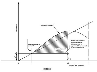
Notes on Figure 1.
(1) Where:
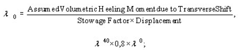
Stowage factor = Volume per unit weight of grain cargo;
Displacement = Weight of ship, fuel, fresh water, stores etc. and cargo.
| (2) | The righting arm curve shall be derived from cross-curves which are sufficient in number to accurately define the curve for the purpose of these requirements and shall include cross-curves at 12 degrees and 40 degrees. |
| (d) | In “partly filled compartments” the adverse effect of the vertical shift of grain surfaces shall be taken into account as follows: |
total heeling moment = 1,12 × calculated transverse heeling moment.
| (e) | Any other equally effective method may be adopted to make the compensation required in paragraphs (c) and (d) above. |