 Businesses Act, 1991 (Act No. 71 of 1991)
R 385
Electronic Communications Act, 2005 (Act No. 36 of 2005)ICASANotice regarding Final Radio Frequency Assignment Plans for the IMT3500 Band in terms of Regulation 3 of the Radio Frequency Spectrum Regulations, 20157. Coordination Requirements |
| 7.1 | Cross Border Frequency Coordination will abide by the Harmonised Calculation Method for Africa (HCM4A) Agreement. This follows the 3rd CRASA AGM that agreed that CRASA should implement the Cross Border Frequency Coordination Harmonised Calculation Method for Africa (HCM4A) Agreement. |
| 7.2 | The ECC had noted the need for greater understanding of the concept and need for harmonisation in the signing of the HCM4A Agreement by the SADC Member States if the implementation of the Agreement is to be effective. The ECC, therefore, agreed to convene a workshop on HCM4A and requested the CRASA Members to consider signing the agreement. These activities were part of the Frequency Planning Sub Committee (FPSC) Operations Plan 2015/16. |
| 7.3 | At the 5th CRASA AGM, Swakopmund, Namibia – 07-08 April 2016 [1], the subject of Cross Border Frequency Coordination using the Harmonised Calculation Method for Africa (HCM4A) was discussed in detail, following similar efforts in Europe. The Resolution CRASA/AGM/15.16/07 stipulates, “The AGM urged CRASA Members to prioritise the motivation to their administrations who are yet to indicate their interest to sign the Harmonised Calculation Method for Africa (HCM4A), to do so as soon as possible”. |
| 7.3.1 | Therefore, coordination would follow the HCM4A as detailed in Sub-Saharan Africa Assessment Report on Harmonisation of ICT Policies in Sub-Saharan Africa2 (HIPSSA]. |
| 7.4 | A harmonised calculation method (HCM4A) brings these benefits: |
| 7.4.1 | Based on HCM Agreement used in Europe; |
| 7.4.2 | Optimise spectrum usage; |
| 7.4.3 | Prevent harmful interferences; |
| 7.4.4 | Confer an adequate protection for stations; |
| 7.4.5 | Define technical provisions and administrative procedures; |
| 7.4.6 | Quick assignment of preferential frequencies; |
| 7.4.7 | Transparent decisions through agreed assessment procedures; |
| 7.4.8 | Quick assessment of interference through data exchange. |
| 7.5 | HCM4A involves all 4 sub regions of Africa. This means the HCM4A projects include performing a survey and a comparative analysis of existing administrative and technical procedures related to bilateral and multilateral cross-border frequency coordination agreements across the 4 geographical sub-regions as defined by the African Union (AU), namely: |
| 7.5.1 | Central Africa [Burundi, Central African Republic, Chad, Congo, Democratic Republic of Congo, Equatorial Guinea, Gabon, Sao Tome, and Principe]; |
| 7.5.2 | East Africa [Comoros, Djibouti, Eritrea, Ethiopia, Kenya, Madagascar, Mauritius, Rwanda, Seychelles, Somalia, Sudan, Tanzania, Uganda]; |
| 7.5.3 | Southern Africa [Angola, Botswana, Lesotho, Malawi, Mozambique, Namibia, South Africa, Swaziland, Zambia, Zimbabwe]; |
| 7.5.4 | West Africa [Benin, Burkina-Faso, Cape Verde, Côte d’Ivoire, Gambia, Ghana, Guinea, Guinea-Bissau, Liberia, Mali, Niger, Nigeria, Sierra Leone, Senegal, Togo]. |
| 7.6 | HCM4A also comes with a software tool for Sub-Saharan Africa 3 |
| 7.6.1 | Optimise spectrum usage by accurate interference field strength calculations; |
| 7.6.2 | Establish general parameters, improvement, and supplementation of technical provisions, individual restrictions; |
| 7.6.3 | Establish models for computer-aided interference range calculations |
| 7.6.4 | Harmonise parameters: objectively predictable towards transparent decisions |
| 7.7 | Use of these frequency bands will require coordination with the neighbouring countries within the coordination zones of 6 kilometres from the neighbouring country. The coordination distance is continuously being reviewed and these may be updated from time to time. |
| 7.8 | New assignments would also require coordination with the existing incumbent assignments. |
| 7.9 | The following field strength thresholds have to be assured. Operator-to-operator coordination may be necessary to avoid interference. |
| 7.10 | The below follows ECC/REC (15)01. |
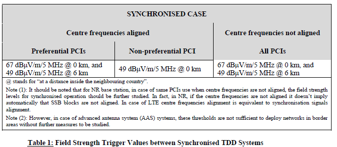
A) TDD, Synchronised case
Base stations of synchronised TDD systems on both sides of the border line with centre frequencies not aligned for all PCIs or with centre frequencies aligned and for preferential PCIs may be used without coordination with a neighbouring country if the mean field strength of each cell produced by the base station does not exceed the values of 67 dBμV/m/5 MHz at a height of 3 m above ground at the border line between countries and 49 dBμV/m/5 MHz at a height of 3 m above ground at a distance of 6 km inside the neighbouring country. Base stations of synchronised TDD systems on both sides of the border line with centre frequencies aligned and for non-preferential PCIs may be used without coordination with a neighbouring country if the mean field strength of each cell produced by the base station does not exceed the value of 49 dBμV/m/5 MHz at a height of 3 m above ground at the border line between countries.
The following table gives an overview of the trigger values of the field strength at a height of 3 m above ground between synchronised TDD systems:
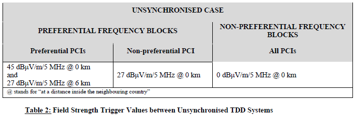
B) TDD, Unsynchronised case
| 1. | Base stations of unsynchronised TDD systems on both sides of the border line for all PCIs may be used without coordination with a neighbouring country if the mean field strength of each cell produced by the base station does not exceed a value of 0 dBμV/m/5 MHz at a height of 3 m above ground level at the border line between countries. If preferential and non-preferential frequency blocks are defined and are distributed between neighbouring countries, the following provisions apply: |
| 2. | Base stations of unsynchronised TDD systems on both sides of the border line with preferential frequency blocks and for preferential PCIs may be used without coordination with a neighbouring country if the mean field strength of each cell produced by the base station does not exceed the trigger values of: |
| • | 45 dBμV/m/5 MHz at a height of 3 m above ground at the border line between countries, and |
| • | 27 dBμV/m/5 MHz at a height of 3 m above ground at a distance of 6 km inside the neighbouring country. |
| 3. | Base stations of unsynchronised TDD systems on both sides of the border line with preferential frequency blocks and for non-preferential PCIs may be used without coordination with a neighbouring country if the mean field strength of each cell produced by the base station does not exceed the trigger values of 27 dBμV/m/5 MHz at a height of 3 m above ground at the border line between countries. |
| 4. | Base stations of unsynchronised TDD systems on both sides of the border line with non-preferential frequency blocks and for all PCIs may be used without coordination with a neighbouring country if the mean field strength of each cell produced by the base station does not exceed the trigger values of 0 dBμV/m/5 MHz at a height of 3 m above ground level at the border line between countries. |
The following table gives an overview of the trigger values of the field strength at a height of 3 m above ground for preferential frequency blocks of unsynchronised TDD systems:
For field strength predictions, the calculations should be made according to Appendix B. In the case of channel bandwidth other than 5 MHz, a factor of 10 x log10 (channel bandwidth[4] /5 MHz), should be added to the field strength levels.
For this band, due to the low field strength level in the unsynchronised case, in order to enable the field strength measurement, a conversion factor of 23 dB from 3 m to 10 m could be applied for suburban environment.
GUIDANCE FOR OPERATORS FOR DEPLOYMENT IN BORDER AREAS
This section lists different techniques as a guidance for operators that can be used to reduce the interference across the border in case of both TDD and FDD systems. In the context of TDD systems, while these techniques decrease the interference, they may not be sufficient to enable unsynchronised operation of TDD networks across the border.
Antenna tilting and restricted beamforming:5 The downtilt of the base station antennas is adjusted such that there is suppression of all signals towards the horizon, thereby reducing the horizon component of interference to the base stations. In the case of advanced antenna system (AAS) antennas at the base stations, configured elevation-domain codeword subset restriction may also be used to decrease the interference to the base stations across the border.
Downlink power reduction: Another possible solution could be to reduce the downlink power on the base station sectors which are facing the border or located at sites near the border. One of the main advantages of this technique is that there is less interference radiated across the border. Moreover, since the difference between the uplink and downlink transmit powers is smaller, there is reduced UL/DL imbalance in a cell. The direct consequence of this technique is that the downlink to uplink interference becomes less problematic as there is a smaller area with vulnerable user equipment (UE). Also, smaller cells can be deployed closer to the border, providing a stronger uplink. Additionally, the performance degradation due to downlink power reduction can be compensated for by link adaptation.
Minimum inter-cell interference scheduling: The selection of start Physical Resource Blocks (PRB) or Resource Block Group (RBG) in the scheduler can be enhanced to reduce the inter-cell interference. This can be accomplished through restricted or randomised distributed PRB scheduling in uplink or RBG scheduling in downlink.
FDD6:
The 3510-3590 MHz band may be used for MFCN FDD systems downlink without coordination if the mean field strength of each cell produced by the base station does not exceed:
• if FDD systems are used in the neighbouring country, a value of 67 dBμV/m/5 MHz at a height of 3 m above ground level at the border line between countries and a value of 49 dBμV/m/5 MHz at a height of 3 m above ground level at a distance of 6 km inside the neighbouring country.
• if TDD systems are used in the neighbouring country, a value of 32 dBμV/m/5 MHz at a height of 3 m above ground level at the border line between countries.
TDD Downlink only scenario should be considered as FDD downlink scenario. For field strength predictions, the calculations should be made according to Appendix B. In cases of other frequency block sizes 10*log10(frequency block size / 5 MHz) should be added to the field strength values.
If neighbouring administrations wish to agree on frequency coordination based on preferential frequencies, whilst ensuring equitable treatment of different operators within a country, the Authority will add these into the mutual agreements.
As per ECC/REC (11)05 of the 26th May 2011, the cross border operation between TDD and between TDD and FDD systems, stations of IMT systems may be operated without coordination if the mean field strength produced by the cell (all transmitters within the sector) does not exceed the value of 21 dBμV/m/5 MHz at 10% time, 50% of locations at 3 metres above ground level at the border line. Adjusting this value by the ratio of the propagation attenuations in the bands, i.e., 20 × log10(3400 MHz / 2500 MHz) = 2.7 dB, the adjusted mean field strength produced by the cell (all transmitters within the sector) does not exceed the value of 23.7 dBμV/m/5 MHz.
| 7.11 | Technical analysis may be conducted by the Authority before an assignment is issued according to Appendix B based on an extract from ECC/REC (15)01. |
| 7.12 | Specific information regarding coordination may be found in Appendix C based on an extract from ECC/REC (11)05 and ECC/REC (15)01. |
| 7.13 | In the event of any interference, the Authority will require affected parties to carry out coordination. In the event that the interference continues to be unresolved after 24 hours, the affected parties may refer the matter to the Authority for a resolution. The Authority will decide the necessary modifications and schedule of modifications to resolve the dispute. The Authority will be guided by the Frequency Coordination Process as shown in Appendix D. |
| 7.14 | Assignment holders will take full advantage of interference mitigation techniques such as antenna discrimination, tilt, polarisation, frequency discrimination, shielding / blocking (introduce diffraction loss), site selection, and/or power control to facilitate the coordination of systems. |
_____________________________________________________________
1https://www.google.com/url?sa=t&rct=j&q=&esrc=s&source=web&cd=&ved=2ahUKEwi81bOFz6P2AhUwQUEAHe1YD IgQFnoECAIQAQ&url=https%3A%2F%2Fextranet.crasa.org%2Fzip-agm.php%3Fid%3D332&usg=AOvVaw1bVAuEnE8a2iJnP20F_b_2
2 https://www.itu.int/en/ITU-D/Projects/ITU-EC-ACP/HIPSSA/Documents/FINAL%20DOCUMENTS/FINAL%20DOCS%20ENGLISH/hcm4a_agreement.pdf.pdf
3 PowerPoint Presentation (itu.int) https://www.itu.int/en/ITU-D/Regional- Presence/AsiaPacific/Documents/Events/2017/May%20BKK/Presentations/HCM%20and%20HCM4A%20B KK%2020170504%20IB.pdf
4 Unoccupied occupied bandwidth
5 https://docdb.cept.org/download/1777
6 As per an older version of ECC/REC/ (15)01 dated 05 February 2016 (the latest version does not include this information).