 Witness Protection Act, 1998
R 385
Electronic Communications Act, 2005 (Act No. 36 of 2005)ICASANotice regarding Final Radio Frequency Spectrum Assignment Plan for the IMT900 Band in terms of Regulation 3 of the Radio Frequency Spectrum Regulations, 2015AppendicesAppendix C: Coordination for IMT-Systems |
Appendix C: Coordination for IMT-Systems
PREFERENTIAL PHYSICAL-LAYER CELL IDENTITIES (PCI) FOR IMT-2000/LTE27
|
The following is extracted from ECC/REC (11)05 as an operational example and can be adapted for the SADC countries for LTE. A respective extract from ECC/REC (15)01 may be considered for expanding the same onto NR. |
PCI coordination is only needed when channel centre frequencies are aligned independently of the channel bandwidth.
3GPP TS 36.21128 defines 168 “unique physical-layer cell-identity groups” in §6.11, numbered 0…167, hereafter called “PCI groups” for LTE. Within each PCI group, there are three separate PCIs giving 504 PCIs in total.
Administrations should agree on a repartition of these 504 PCIs on an equitable basis when channel centre frequencies are aligned, as shown in the table below. It has to be noted that dividing the PCI groups or PCIs is equivalent. Each country should only use their own preferential PCIs close to the border and can use all PCIs away from the border. This transition distance between “close to the border” and “away from the border” should be agreed between neighbouring countries.
Administrations may wish to define different field strength levels (than those provided in the main text referring to this Appendix) for non-preferential PCIs.
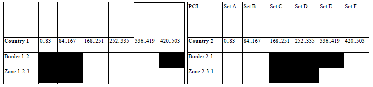
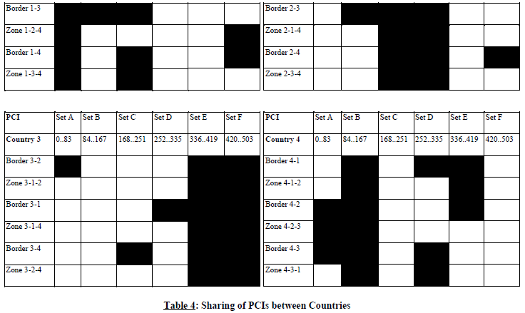
As shown in the table below, the PCIs should be divided into 6 sub-sets each containing one sixth of the available PCIs. Each country is allocated three sets (half of the PCIs) in a bilateral case and two sets (one third of the PCIs) in a trilateral case.
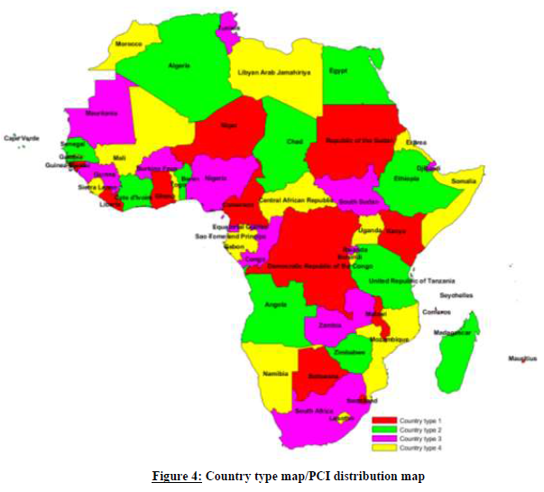
Four types of countries are defined in a way such that no country will use the same code set as any one of its neighbours. The following lists describe a sample distribution for African countries:
Country type 1: Botswana, Cameroon, Comoros, Democratic Republic of the Congo, Ghana, Guinea-Bissau, Kenya, Liberia, Malawi, Mauritius, Niger, Republic of the Sudan, Swaziland;
Country type 2: Algeria, Angola, Benin, Cape Verde, Chad, Cote d'Ivoire, Egypt, Ethiopia, Madagascar, Senegal, United Republic of Tanzania, Zimbabwe;
Country type 3: Burkina Faso, Congo, Djibouti, Equatorial Guinea, Guinea, Mauritania, Nigeria, Rwanda, São Tomé and Príncipe, Seychelles, South Africa, South Sudan, Tunisia, Zambia;
Country type 4: Burundi, Central African Republic, Eritrea, Gabon, Gambia, Lesotho, Libyan Arab Jamahiriya, Mali, Morocco, Mozambique, Namibia, Sierra Leone, Somalia, Togo, Uganda.
(Note: A sample country type map can be found in the figure below).
For each type of country, the following tables and figure describe the sharing of the PCIs with its neighbouring countries, with the following conventions of writing:
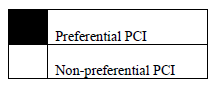
The 504 physical-layer cell-identities should be divided into the following 6 sub-sets when the carrier frequencies are aligned in border areas:
Notes
| (1) | All PCIs are available in areas away from the border. |
| (2) | In certain specific cases (e.g., if Angola and Botswana happened to have the same Country type/PCI code) where the distance between two countries of the same type number is very small (below a few tens of kilometres), it may be necessary to address the situation in bilateral /multilateral coordination agreements as necessary and may include further subdivision of the allocated codes in certain areas. |
GUIDANCE ON THE CONSIDERATION OF LTE RADIO PARAMETERS FOR USE IN BILATERAL AND MULTI LATERAL AGREEMENTS
This section is provided for guidance purposes for use in bi-lateral and multilateral discussions. For LTE, it may be beneficial to coordinate other radio parameters besides PCI in order to minimise deteriorating effects of uplink interference.
The parameters described in this section are usually optimised during LTE radio network planning of an operator’s network. The idea of optimisation is to plan the parameters taking into account specific correlation properties of the uplink control signals, which enable more stable and predictable operation of the network. In the cross-border scenario the optimisation of parameters among neighbouring operators could provide better control of uplink interference. However, because of the difference between intra-network and inter-network interference and due to limited experience in the LTE cross-border deployment, it is difficult to assess the benefits of such optimisation. The following guidance provides the basis for operators to consider in border areas in cases of high levels of uplink interference.
| 1. | Demodulation Reference Signal (DM RS) coordination |
Demodulation reference signals (DM RS) are transmitted in the uplink and used for channel estimation. There is a risk of intercell interference between neighbouring cells even in case of no frame synchronisation. That is why special measures for DM RS allocation between networks in neighbouring countries occupying the same channel may need to be applied.
The case of partial channel overlap has not been studied but due to DM RS occupying resource blocks of separate users there is a risk of DM RS collisions between neighbouring networks when the subcarriers' positions coincide (the frequency offset between central carriers of neighbouring networks is a multiple of 300 kHz). Some minor benefits from DM RS coordination in these particular cases could be expected.
There are a number of possible approaches to the coordination of DM RS:
| • | In the basic planning procedure, only 30 DM RS sequence groups with favourable correlation characteristics are available: {0…29}. In this case, each cell could be assigned one of the 30 DM RS sequence groups providing a cluster size of 30. |
| • | It is possible to extend each DM RS sequence group to generate up to 12-time shifted sequence groups by applying the cyclic shift parameter stated in 3GPP TS 36.21129 for LTE. For example, each tri-sector site could be assigned one DM RS sequence group with each co-sited cell having its own cyclic shift of 2π/3, which provides cluster size 30 with only 10 DM RS sequence groups. The latter case corresponds well to the case of DM RS sequence group repartition between neighbouring countries when only a limited number of groups is available for network planning. The drawback of DM RS sequence group cyclic shift is a loss of orthogonality of DM RS due to fading channels which has been found during first trials of LTE and caused throughput loss as well as time alignment problems. |
| • | Another approach for DM RS coordination is to implement dynamic DM RS sequence group allocation also called pseudo-random group hopping. In this method nearby cells are grouped into clusters up to 30 cells and within each cell cluster, the same hopping-pattern is used. At the border of two clusters, inter-cell interference is averaged since two different hopping patterns are utilised. There are 17 defined hopping patterns, numbered {0…16}, which leads to some minor unfairness in the case of apportioning these patterns between neighbouring countries. Even in a trilateral case, each operator will have at least 5 hopping patterns available near the border, which should be enough for planning purposes. It should be noted the pseudo-random group hopping option could be absent in the first generations of LTE equipment. |
The decision of which of these methods to use in cross-border coordination should be agreed upon by the interested parties. Specific DM RS sequence groups or hopping pattern repartition is not provided in this text but could be deduced in a similar manner to the PCI repartition.
| 2. | Physical Random-Access Channel (PRACH) coordination |
Another radio network parameter that is considered during radio network planning is PRACH configuration which is needed to distinguish random access requests addressed to different cells. PRACH resources are allocated by specifying the PRACH Resource Blocks time positions within the uplink frame, their frequency position within the LTE channel bandwidth and by apportioning cell specific root sequences. During radio network planning these parameters are usually used in the following way:
| • | Time positions for PRACH resource allocations are usually used to create time collision of PRACH resources of co-sited/frame synchronised cells because PRACH-to-PRACH interference is usually less severe than PUSCH-to-PRACH interference; |
| • | Frequency positions within the LTE channel bandwidth are usually the same for all cells, again because the PRACH-to-PRACH interference case is a more favourable one. |
| • | Cell-specific root sequences are used to distinguish between PRACH requests addressed to different cells. |
For cross-border coordination, it is proposed to use frequency position offsets to exclude the possibility of so-called “ghost” PRACH requests caused by neighbouring networks. The PRACH is configured in LTE to use only 6 Resource Blocks or 1.08 MHz of the LTE channel bandwidth except in regions used by PUCCH. In case of overlapping or partially overlapping channel bandwidths of neighbouring networks, it is enough to establish non-overlapping PRACH frequency blocks to perform coordination. Because it is difficult to establish an implementation dependent procedure for such allocation, it will be the responsibility of operators to manage such frequency separation during coordination discussions.
In an early implementation, it is possible that a very limited number of frequency positions could be supported by LTE equipment which will not be enough to coordinate in the trilateral case. In such cases, root-sequence repartition could be used. There are 838 root sequences in total to be distributed between cells, numbered {0…837}. There are two numbering schemes for PRACH root sequences (physical and logical), and only logical root sequence numbering needs be used for coordination. Unfortunately, the process of root sequence planning doesn’t involve direct mapping of root sequences between cells because the number of root sequences needed for one cell is dependent on the cell range. The table showing such interdependency is presented below:

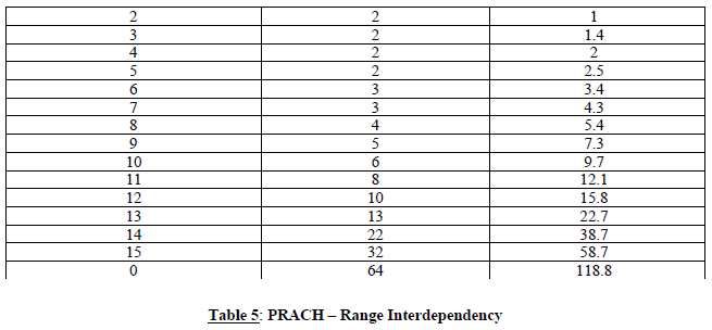
Thus, in the case of root sequence reparation, it will be the responsibility of radio network planners to assign the correct number of root sequences in order to not overlap with the root sequence ranges of other operators. It also should be noted that different root sequences have different cubic metrics and correlation properties, which affect PRACH coverage performance and planning of so-called high-speed cells. For simplicity of cross-border coordination, it is proposed to ignore these properties.
In summary, it should be stipulated that frequency separation of PRACH resources should be used as the main coordination method. PRACH root sequences repartition should be avoided and used only in exceptional cases. Specific PRACH root sequences repartition is not provided in this text but could be deduced in a similar manner to the PCI repartition.
Additional guidance for cross-border coordination of synchronised and unsynchronised LTE and 5G/NR TDD systems may be found in ECC/REC/ (15)0130 and ECC Report 296 31. The text above is based on these.
____________________________________
| 27 | ECC/REC (11)05. |
| 28 | 3GPP TS 36.211 “Evolved Universal Terrestrial Radio Access (E-UTRA); Physical channels and modulation”. (https://portal.3gpp.org/desktopmodules/Specifications/SpecificationDetails.aspx?specificationId=2425 , also provided in ETSI TS 136 211). In comparison, 3GPP 38.211 (and ETSI TS 138 211) define NR Physical channels and modulation, in NR 2-step identification using PSS/SSS detection of the Physical Cell ID (same as LTE), the number of different cell IDs has been increased from 504 in LTE to 1008 for NR. Thus, for the deployment of LTE systems only the PCIs between 0 to 503 should be used and for NR systems PCIs between 0 to 1007 may be used. |
| 29 | https://portal.3gpp.org/ngppapp/DownloadTDoc.aspx?contributionUid=R1-1613067. |
| 30 | ECC Recommendation (15)01 “Cross-border coordination for Mobile/Fixed Communications Networks (MFCN) in the frequency bands: 694-790 MHz, 1427-1518 MHz, and 3400-3800 MHz”. Amended on 14 February 2020. |
| 31 | ECC Report 296: “National synchronisation regulatory framework options in 3400-3800 MHz: a toolbox for coexistence of MFCNs in synchronised, unsynchronised, and semi-synchronised operation in 3400-3800 MHz”, March 2019. |